Building IrDA transceiver for PC-motherboard
| home | ||
| Building IrDA transceiver for PC-motherboard | ||||||||
|
|
This page is obsolete and provided for historical reference only. You can find up-to-date information about embedded systems and microcontrollers on www.embedeo.org. This article explains how to build and add an IrDA-compatible transceiver (a.k.a. Infra Red Eye) for PC motherboard. It allows connection between computer and an IrDA compatible device, such as cellular phone, for example. If you need to use a regular remote (from TV, CD etc.) to control your computer, than this page is not for you, you'd better start from www.lirc.org. If you are going to add IR connectivity to the parallel port of your PC take a look at http://www.ziplabel.com/cir/index.html |
- last updated: |
The information on this page is provided in the hope that it will be useful, but WITHOUT ANY WARRANTY; without even the implied warranty of MERCHANTABILITY or FITNESS FOR A PARTICULAR PURPOSE. Use the information at your own risk. Reasons Most of the modern computer motherboards have an IR header, which usually shares resources with one of the serial ports. The header itself is not enough to communicate with external IR device. A special optoelectronical unit is needed, and that is the transceiver described below. I have found a couple of design solutions but most of them were not suitable enough, due to either of: Schematic
It looks a little bit encumbered at a glance but in fact SMD-assembled unit is as small as commercial unit. U1 just forms RxD edges, and only one of six Schmitt triggers is needed. If you find it confusing, you may redesign the trigger with discrete elements. Actualy, 40106 is very cheap, and also other kind of IC with Schmitt triggers, like 74LS14 should fit without problem. Note, that your motherboard could require inverse signal RxD, so you should use a noninverting Schmitt triger or remove the group of T4, R6, R7. In the second case it is not possible to use 40106 but an other kind of trigger with better load capabilities, and certainly you should be willing to experiment.
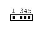
BIOS setup Usually, the PC motherboards have a shared serial port set to regular COM1/COM2 by default, or at least their IR port header is disabled. You should refer to the manual of the motherboard, and enable its IR capabilities. The transceiver, described here, is intended to work with the so called SIR modulation. (You can find more information at www.irda.org.) That was marked as HPSIR in the BIOS settings of my motherboard, for example. You must refer to the specification of your motherboard how to handle that. Setting up HALF DUPLEX mode is also recommended. Header connection example The drawing below represents the IR Header of a GA-7DXR+ motherboard from GIGABYTE.
This is just an example. Refer to your motherboard's manual for actual pin assignment! Feedback It will be useful if I add more practical information, such as - Motherboard's IR header pin assignment and BIOS settings for popular models etc. but I can't promise I'll do that. Anyway I'll appreciate any interesting experimental feedback. |
|
Most of the pictures are made in GIMP environment. |
Copyright (C) 2003 Dimo Dimov |